Optical Fiber

What are optical fibers?
Data transfer via light instead of current
An optical fiber is a delicate fiber from plastic or glass that can transfer optical signals in the form of light (waves) over long distances without an amplifier*. Whereas with copper lines it is electrical signals that travel the distance as electrons, with fiber optics it is photons (light particles) that travel. Data transmission takes place at the speed of light - the light waves propagate through the fiber. Fiber optics enable enormous bandwidths, one of their greatest advantages. In the following, you can learn more about the transmission medium of the future. (* For long distances, you may require repeaters.)
Content
How ist an optical fiber constructed?
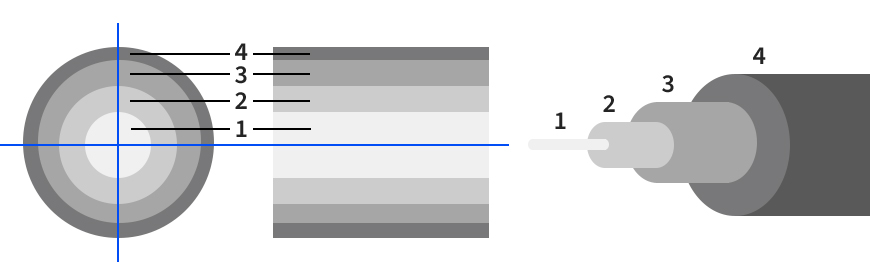
A fiber with four layers
[1] The fiber core / core glass as the central area serves the waveguiding of the light. The core consists of a material with a higher refractive index (optical density) than the cladding above it.
[2] The cladding consists of optically transparent material with a lower refractive index than the core. At the boundary layer between the core and cladding, and thus at the walls of the optical waveguide, so-called total internal reflection takes place as an effect of the different refractive indices. Total reflection enables the light beam can be guided with almost no loss.
[3] The coating is applied to the surface of the jacket as mechanical protection and is usually made of plastic.
[4] The buffering / jacket is the outer sheath of the optical fiber and is applied to the coating as a protective material. It protects the fiber from mechanical damage and moisture and usually consists of a coating with special plastics. Buffering is also available as tubes that insulate the fiber from stresses in the cable when the cable is moved.
Fiber optic cables, for example, are made of a bundle of fiber optic fibers with a glass core to provide high-speed Internet. A single optical fiber inclusive cladding has a diameter of about 0.1 mm, slightly thicker than a human hair (of a European). FO fibers are extremely flexible, but also sensitive.
Which advantages do optical fibers offer?
Fiber optic cables, unlike copper cables, have an extensive list of advantages:
- higher range
- higher transmission bandwidth
- longer lifetime
- higher eavesdropping security
- low weight and small space requirement
- does not cause electromagnetic interference
- insensitive to electromagnetic interference
- low attenuation - long transmission distances possible
- also suitable for hazardous areas, as potential-free
- higher immunity to interference: FO can even be laid parallel to (power) supply lines
What are the applications of fiber optics?
The main application area of OF Technology is communication engineering or telecommunication: Optical fibers are the transfer medium of line-bound communication systems at (glass-) fiber optic networks. These systems contain public wide area networks (WAN), company-own local area networks (LAN), and home networks. Optical fibers enable much higher ranges and transmission rates than systems based on copper conductors and have them already replaced, to a large extent, in the communication networks mentioned. Additionally, there are further scopes of use of optical fibers:
- measurement technology: as a component of fiber optic sensors, on spectrometers, and other optical measuring devices
- for the transport of laser radiation for material processing
- in the medical field for illumination and imaging technology, for example, as image conductors in endoscopes
- generally for lighting devices and buildings, for decorative purposes
Are there disadvantages when using optical fibers?
In general, optical fiber cabling is a cost expensive connection, which is the largest disadvantage at the same time. Optical fibers are more expensive than copper conductors. Material and fabrication costs are higher, as also the effort for mounting, connections, and plugs. An optical-electrical signal converter may be necessary which causes costs, too.
Fiber optic fibers are sensitive and can only be bent, kinked, or rotated to a limited extent. Equipped with an appropriate cladding, glass fiber cables from optical fibers are reliably protected against water, oil, acid, or mechanical stress, too. All in all, the advantages of optical fibers outweigh in contrast to copper conductors. Anyway, for the bandwidth and data rates enabled by fiber optic connections, this technology is irreplaceable in the field of current communication engineering.
Optical fiber cable variants and connection options
Different variants of optical fiber cables
Optical fiber cables generally differ by their place of use. There are indoor, outdoor, and universal cables that can be laid in the inner and outer areas. Indoor and outdoor cables with different names, for example, fanout, loose tube, and splitter cables serve the signal and data transmission. Outdoor cables are often rougher, more resistant to weather influences, and secured against rodent bites.
Depending on the kind of application, there are further differentiations. Pigtails are short connection cables with a pre-confectioned and open end each. Patch cables are variable, not fixed-laid, and have mostly a low length. With these, you can cable optical fiber patch fields or the network cabinet, or they connect single devices.
For the permanent installation, for example in buildings or riser lines, or between buildings, there are OF-mounting and installation cables. In contrast, other kinds of cables are regularly moved during the application, for example, in robots or machines. It results in different requirements for robustness and elasticity.

Optical fiber connection methods
You can connect fiber optic fibers firstly by plug connections or, secondly, by the splicing process. With a pigtail you can splice plug connections to an installation cable. Glass fibers can be connected by splicing. In this case, either the two ends of two optical fibers are melted together. That is the so-called melting splice. Or, the ends of the fibers are glued together: This is how the glue splice is formed. Splicings can be made with the help of splice devices.
Connector shapes of optical fibers
The most common connector shapes are briefly explained below. There are also other fiber optic connectors.
SC connector
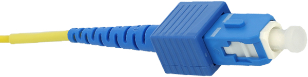
"SC" stands for Subscriber Connector. The SC connector has a locking mechanism (push-pull) so that the cable has a firm hold and does not come loose: the connector locks automatical when inserted and unlocks again when removed. The SC connector is both single-mode and multi-mode compatible (for single- and multi-mode see below).
LC connector
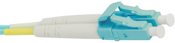
The LC connector, Local Connector, is the successor of the SC connector and is often used in larger data centers. It is a small form factor connector. Its compact design makes it easy to install in the network cabinet. It requires less space and thus allows a higher port density.
ST connector
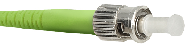
The ST connector (Straight Tip) has a low attenuation and is also known as BFOC connector (Bayonet Fiber Optic Connector) due to its bayonet closure. At that time it had replaced the F-SMA connector, was mainly used in the LAN area, and, was still the standard connector around 2002. But even today it is still frequently used in local networks. The ST connector is both single-mode and multi-mode capable. (for single- and multimode see below).
LSH connector / E-2000

E-2000 is the trademark for the standardized LSH connector. It is a widely used standard connector. Similar to the LC connector, it is unlocked by a lever. The integrated cap protects the connector from dust and dirt as well as from harmful laser beams. It can be used for single-mode and multi-mode fibers.
MTRJ connector
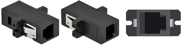
The name of the MTRJ multi-fiber connector is based firstly on the MT (Mechanical Transfer) ferrule for two fibers that it has; and secondly on the shape of an RJ45 connector. It also resembles it in its dimensions and the way it is locked. The MTRJ connector is suitable for both single-mode and multi-mode fibers. It can accommodate up to eight fibers simultaneously.
MPO connector

The MPO (Multipath Push-On) or Multi-Fiber Push-On is a multi-fiber connector for single-mode fibers and multi-mode fibers that can accept 4, 8, 12, 24, 36, 48, 72, 96 or 144 optical fibers. MPO connectors are comparable in size to the RJ45 connector. MPO connectors feature very high density, take up little space, simplify network design, and have extremely high connection density.
(* Image MPO plug front view: Licensed under Creative Commons License, Author: Reichle & De-Massari, source image file here, edited: cutted out)
Fiber types in optical fibers and their categories
There are two types of fiber optic cables: single-mode and multi-mode fibers. These two types are divided into different categories in order to be able to specify the transmission properties and application areas of the diverse fibers. For single-mode fibers there are the categories OS1 and OS2. For multi-mode fibers there are the categories OM1, OM2, OM3, OM4 and OM5. The categories are subject to international standardization.
Differences between single-mode and multi-mode fibers
The differences between single-mode and multi-mode fibers are 1. distance, 2. light source and wavelength, 3. core diameter, and 4. bandwidth.
1. Distance
Single-mode fibers are used for longer distances up to several kilometers and multi-mode fibers for shorter distances up to a few hundred meters. There is a tendency for fiber optic cabling applications with single-mode fibers to be more suitable for long-range data transmission systems. Multi-mode fiber optic cabling systems, on the other hand, are primarily used in companies, data centers, and LANs due to their shorter range.
2. Light source and wavelength
Single-mode fibers enable the spread and transmission of one light type at a time. Multi-mode fibers can transmit several light types (= modes). The wavelengths of single-mode fibers are generally 1310 to 1550 nm (nanometers*), and the wavelengths of multi-mode fibers are 850 to 1310 nanometers.
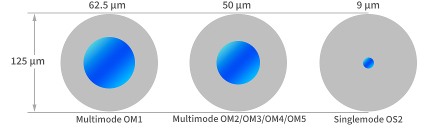
3. Core diameter
Multi-mode fibers usually have a core diameter of 50 µm (micrometers*). The typical core diameter of single-mode fibers is much smaller at 9 µm. The cladding diameter of 125 µm is the same for both fiber types.
4. Bandwidth
The highest bandwidth on multi-mode fibers is 28,000 MHz * km. You can reach this with the multi-mode fibers category OM5. The bandwidth of single-mode fibers is unlimited: One light mode goes through these.
Single-mode fibers
Single-mode fibers, also called mono-mode fibers, are characterized by an extremely small diameter of the fiber core. This core diameter is usually 9 µm (micrometers) and is thus only a few times larger than the wavelength of light. Single-mode fibers have extremely low attenuation and enable very high distances and bandwidths.
Single-mode fibers categories OS1 and OS2
Single-mode fibers are categorized as OS1 and OS2, where OS stands for Optical Singlemode in each case. The OS1 fiber is applicable for use inside on shorter routes, for example, in data centers with a maximum distance of 10 km. The OS2 fiber has a loose-tube construction which is designed for use outside and at longer distances of up to a maximum of 200 km.
Multi-mode fibers
In comparison to the single-mode fibers, the core diameter of multi-mode fibers is significantly larger. It is regularly 50 or 62.5 µm and allows the spread of several light modes. These fibers are applied for short routes. Multi-mode fibers have a higher density and a lower bandwidth than single-mode fibers.
Multi-mode fibers categories OM1, OM2, OM3, OM4, OM5
There are five sorts of multi-mode glass fiber cables: OM1, OM2, OM3, OM4 and OM5. The letters OM stand for Optical Multimode. Every category of multi-mode fiber has a minimal Modal Bandwidth (MBW) requirement.
OM1 fiber This fiber usually has an orange coating with a core dimension of 62.5 µm. This kind of fiber can support 10 Gigabit Ethernet on lengths of up to 33 meters. It is mostly used for 100 Megabit Ethernet applications.
OM2 fiber It has also an orange cladding, but a smaller core size of 50 µm instead of 62.5 µm. The fiber supports 10 Gigabit Ethernet at lengths of up to 82 meters. More often, however, it is used for 1 Gigabit Ethernet applications.
OM3 fiber This fiber has the cladding color aqua and a core size of 50 µm. It supports 10 Gigabit Ethernet at lengths up to 300 meters. It can also support 40 Gigabit and 100 Gigabit Ethernet up to 100 meters. It is most commonly used for 10 Gigabit Ethernet.
OM4 fiber This type of fiber also has the sheath color aqua or even an erica violet color and a 50 µm core. It supports 10 Gigabit Ethernet at lengths up to 550 meters. It also supports 100 Gigabit Ethernet at routes up to 150 meters.
OM5 fiber The big difference between OM1 to OM4, on the one hand, and OM5, on the other hand, is that the first four fiber types operate with only one wavelength range. OM5, on the other hand, additionally uses video band multimode fiber technology (WBMMF), which allows multiple wavelengths to be transmitted. This, in turn, enables transmission rates of up to 400 Gigabits per second, at lengths of up to 150 meters. OM5 cables have a lime green jacket color.
Potential sources of errors in fiber optic transmissions
Problems can occur with a fiber optic connection for many reasons. Here are some common causes:
- Too small a bend radius - light leakage occurs
- Poor splice connection
- Damage or contamination of the coating
- Poor damping ratio (small cracks in the fiber surface)
Delock OF accessories
In the area of fiber optics, Delock offers cables, couplers, and adapters as well as junction boxes, cassettes, patch panels, and distributors. Furthermore, there are articles for cleaning and other accessories. In the following some examples.
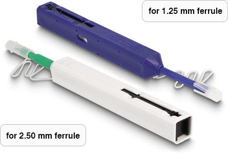
Item 86840
Cleaning pen for connectors with 1.25 mm ferrule
Cleaning pins are suitable for fast and thorough cleaning of fiber optic connectors (LC and MU) to remove dirt particles such as dust in the sleeves of the connectors.
Also available as Item 86841 with 2.50 mm ferrule.
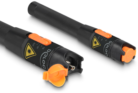
Item 87217
Visual fault locator 10 mW for SC / LC / ST / FC connectors
The fiber optic tester for single and multi-mode fibers is made to check and precisely measure connections. It detects whether the light beam is transmitted correctly and quickly finds breaks, contamination, or cracks in the fiber optic cable.

Item 87285
Cleaning Cassette for connectors with 1.25 and 2.50 mm ferrule
This practical cleaning cassette quickly and thoroughly removes impurities and dirt particles such as dust in the ferrules of the connectors. Suitable for SC, LC, FC MU and E2000 connectors; for up to 550 cleaning operations.
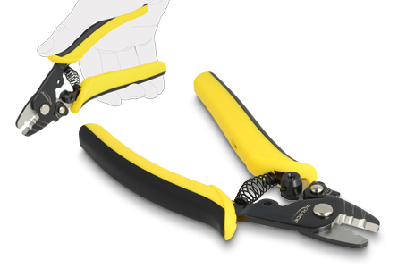
Item 90552
Wire stripper for OF cable
The metal pliers with a soft handle made of non-slip material have three openings with which the 2 mm thick outer jacket, the 900 µm solid core as well as the 250 µm acrylate coating can be stripped.
Delock's optical fiber product range is constantly expanding. The complete range around optical fibers here.